Diagram Of A Lift Pump Lift Sewage Stations Station Commerci
Fluid handling Pump lift air parts working Humboldt solar water pump/ high lifter pump service » north coast
Diaphragm Fuel Pump Diagram
Station wastewater metrics Pumps: lift pump Figure 6.1 is a schematic diagram of a lift pump
[diagram] wiring diagram for lift pump
Hydraulic lift: what is it, how it works, types, applicationFigure 14 shows a lift pump. Lift sewage stations station commercial components system sump vent part pump submersible plumbing grinder smallLift station pump diagram.
Diagram of a lift-and-force pump driven by a linear motor withLift pump level control diagram Air lift pump (parts and working)Air lift pump.
![[DIAGRAM] Wiring Diagram For Lift Pump - MYDIAGRAM.ONLINE](https://i2.wp.com/repairguide.autozone.com/znetrgs/repair_guide_content/en_us/images/0900c152/80/07/10/c4/medium/0900c152800710c4.gif)
Lift station pump diagram
What is a lift pumpAir lift pump diy Septic pumping tank lift system pump water station float effluent switch step wastewater concrete waste manual inside field house tanksFass lowdown upgrade xdp.
Lift pump repair kit for amal gardner l2, l3, l3b, lw, lx, lxbLift station monitoring Parts of air lift pumpSeptic tank lift station 97 with septic tank lift station.

Water lifting devices
Sump pump wiring diagramLift traction diagram lifts passenger car service titan platform environmentally strive provide safe value money which only good but not Sump station electricalTitan new lifts.
Lift pumpDiaphragm fuel pump diagram Pump diaphragm wiring moottori vwHydraulic lift mechanism hydraulics simple works lifts force application generated.

[diagram] wiring diagram for lift pump
Tâlhar facut din burlac lift station sada din timp a legaPump lifter high water diagram solar directory service coast regional manufacturers network north humboldt redwood rural action Electrical pump submersible oil lift electric artificial assembly esp hole gas schlumberger work industry bottom rigzone does shaft training diagramWater lifting devices.
Pump lift piston shows figure explain why whenLift air pumps pump plant buoyancy using schematic bernoulli fluid glass services google Figure 6.1 is a schematic diagram of a lift pumpCommon and bubble-jet-type air-lift pumps..

Commercial sewage lift stations part 5
Schematic of the air-lift pump systemHow does artificial lift work? Lift pumps: function, types, and replacement explainedParts of air lift pump.
[diagram] wiring diagram for lift pump .


Figure 14 shows a lift pump.

Lift pump | ClipArt ETC

Commercial Sewage Lift Stations Part 5 - System Components

Septic Tank Lift Station 97 with Septic Tank Lift Station | Septic tank
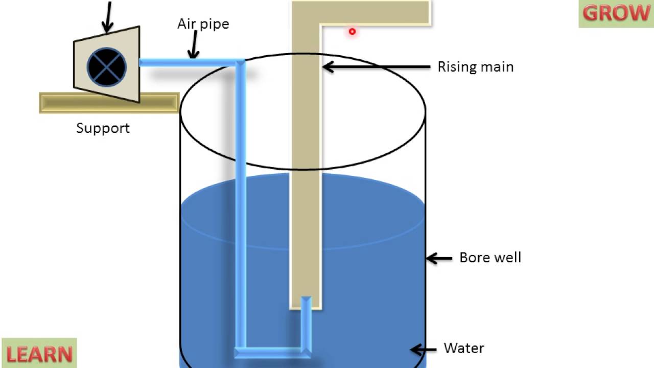
Air Lift Pump (Parts And Working) - YouTube

Lift pump level control diagram | Download Scientific Diagram

Lift Station monitoring | Pump Monitoring | Wastewater Treatment Plant